Surface Mount Technology Quick and Easy Explanation in 2026
Published: 8 Dec 2025
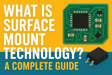
Surface Mount Technology, also known as SMT, is one of the most important manufacturing methods in the electronics industry. Almost every modern electronic device uses SMT because it helps manufacturers build smaller, faster, and more reliable products. Smartphones, laptops, smart watches, gaming consoles, medical devices, automotive systems, and industrial machines all depend on this technology.
Today, SMT is the standard assembly process used by electronics manufacturers around the world. It supports automated production, reduces manufacturing costs, improves electrical performance, and allows engineers to design compact electronic products with advanced features.
In this guide, you will learn everything about Surface Mount Technology, including its history, common SMT terms, manufacturing process, assembly techniques, advantages, disadvantages, component packages, inspection methods, and future trends.
What Is Surface Mount Technology (SMT)?
Surface Mount Technology, or SMT, is a manufacturing process in which electronic components are mounted directly onto the surface of a Printed Circuit Board instead of inserting their leads through drilled holes. Components designed for this process are called Surface Mount Devices, or SMDs.
Unlike traditional assembly methods, SMT allows components to be placed on both sides of a PCB. This increases component density while reducing the overall size of the circuit board. Because components are smaller and placed closer together, electronic devices become lighter, faster, and more energy efficient.
Most SMT production lines use advanced automated machines to place thousands of components every hour with outstanding accuracy. This automation improves production speed while reducing human error.
Why Is SMT Important?
Surface Mount Technology has become the preferred manufacturing process because modern electronic products require compact designs and high performance. Manufacturers can build advanced devices without increasing their physical size.
SMT also supports high speed communication circuits, powerful processors, and modern wireless technologies by reducing electrical interference caused by long component leads.
Some of the biggest reasons why SMT is important include:
- Smaller electronic devices
- Faster manufacturing
- Lower production costs
- Better electrical performance
- Higher reliability
- Improved automation
- Greater design flexibility
Without SMT, many of today’s portable electronic products would not be possible.
Main Components Used in SMT
Several electronic components are specially designed for Surface Mount Technology. These include:
- Surface mount resistors
- Surface mount capacitors
- Integrated circuits
- Diodes
- LEDs
- Transistors
- Inductors
- Connectors
- Crystal oscillators
Each component is manufactured with small metal terminals that can be soldered directly onto PCB pads.
History and Evolution of SMT
The history of Surface Mount Technology dates back to the 1960s when electronics manufacturers started searching for more efficient ways to assemble printed circuit boards. Traditional Through Hole Technology worked well, but it limited miniaturization and slowed mass production.
Early research into surface mounting introduced the idea of attaching components directly to the PCB surface instead of inserting them through holes. During the early years, the technology was mainly used in military and aerospace electronics because these industries required lightweight and reliable circuits.
The biggest breakthrough came during the late 1970s and early 1980s. Electronics companies began producing smaller components that could easily be mounted on PCB surfaces. Automated pick and place machines also became more accurate, making large scale SMT manufacturing practical.
As personal computers, consumer electronics, and communication devices became popular during the 1980s and 1990s, Surface Mount Technology quickly replaced most traditional assembly methods.
Today, nearly every electronic manufacturing company uses SMT because it offers better production speed, improved quality, and lower manufacturing costs.
Common SMT Abbreviations
When learning about Surface Mount Technology, you will often see these abbreviations.
SMT stands for Surface Mount Technology. It refers to the complete manufacturing process.
SMD means Surface Mount Device. These are the electronic components designed for SMT.
SMC stands for Surface Mount Component. It is another name for an electronic component used in SMT.
SMA means Surface Mount Assembly. This refers to a PCB after surface mount components have been assembled.
PCB stands for Printed Circuit Board, which acts as the foundation for all electronic components.
Understanding these terms makes it much easier to read technical documents and communicate with PCB manufacturers.
How SMT Has Changed Electronics
Surface Mount Technology has transformed electronics manufacturing in several ways.
Manufacturers can now produce millions of electronic products with consistent quality. Devices have become smaller while offering greater processing power. Modern smartphones contain thousands of SMT components placed on extremely compact circuit boards.
Medical equipment has also improved because SMT allows portable diagnostic devices and wearable health monitors to become more compact and reliable.
In the automotive industry, SMT supports advanced driver assistance systems, infotainment systems, electric vehicles, and engine control units.
Industrial automation also benefits from SMT because factories require reliable electronic controllers that can operate continuously under demanding conditions.
As artificial intelligence, robotics, Internet of Things devices, and 5G communication continue to expand, Surface Mount Technology will remain one of the most important manufacturing processes in the electronics industry.
Common SMT Terms and Abbreviations
Surface Mount Technology uses several technical terms that are common in PCB manufacturing. Understanding these abbreviations helps engineers, technicians, students, and electronics manufacturers communicate more effectively.
SMT (Surface Mount Technology)
SMT stands for Surface Mount Technology. It is the complete manufacturing method where electronic components are mounted directly onto the surface of a Printed Circuit Board instead of inserting their leads through drilled holes. Today, SMT is the standard assembly process used in almost every electronics manufacturing facility.
SMD (Surface Mount Device)
A Surface Mount Device is an electronic component specifically designed for SMT assembly. Unlike traditional through hole components, SMDs have small metal terminals that connect directly to solder pads on the PCB.
Common SMD components include:
- Resistors
- Capacitors
- Diodes
- LEDs
- Transistors
- Integrated Circuits
- Inductors
- Crystal Oscillators
These components are available in many different package sizes depending on the application.
SMC (Surface Mount Component)
SMC means Surface Mount Component. The term has the same meaning as SMD and is commonly used in technical documents and manufacturing environments.
SMA (Surface Mount Assembly)
SMA refers to a Printed Circuit Board after all surface mount components have been assembled and soldered successfully.
PCB (Printed Circuit Board)
A Printed Circuit Board is the base platform that holds electronic components together. Copper traces on the PCB connect all electronic components and allow electrical signals to flow throughout the circuit.
How Surface Mount Technology Works
Surface Mount Technology follows a highly automated manufacturing process. Every step is carefully controlled to ensure high quality, accurate component placement, and reliable solder joints.
The process begins with a bare PCB and ends with a fully assembled electronic board ready for testing.
Step 1. PCB Preparation
The first step is preparing the Printed Circuit Board.
The PCB contains copper pads where components will be mounted. Before assembly begins, the board is cleaned carefully to remove dust, moisture, oil, and contaminants that could affect solder quality.
A clean PCB helps create stronger solder joints and improves manufacturing reliability.
Step 2. Solder Paste Printing
After PCB preparation, solder paste is applied to the board.
A stainless steel stencil is placed over the PCB, and solder paste is spread across it using a squeegee. The stencil allows solder paste to reach only the required solder pads.
The solder paste contains tiny solder particles mixed with flux.
Its purpose is to:
- Hold components temporarily
- Create electrical connections
- Form strong solder joints during heating
This step is one of the most critical stages in SMT production because incorrect solder paste printing can cause defects later in the process.
Step 3. Component Placement
Once solder paste has been applied, automated Pick and Place machines position Surface Mount Devices onto the PCB.
Modern placement machines use high speed cameras and computer vision systems to identify every component before placing it.
These machines can place tens of thousands of components every hour while maintaining excellent accuracy.
The machines automatically detect:
- Component orientation
- Component size
- Placement position
- PCB alignment
Accurate placement is essential because even a tiny positioning error can cause circuit failure.
Step 4. Reflow Soldering
After all components have been placed, the PCB moves into a Reflow Oven.
The oven gradually heats the board through several temperature zones.
During heating:
- Flux activates.
- Solder paste melts.
- Molten solder forms electrical connections.
- Solder cools into permanent joints.
This process permanently attaches every component to the PCB.
A properly controlled reflow profile produces reliable solder joints with excellent electrical performance.
Step 5. Inspection and Testing
Quality inspection is performed after soldering.
Manufacturers use several inspection methods to detect assembly defects before products reach customers.
Common inspection methods include:
- Automated Optical Inspection (AOI)
- X-Ray Inspection
- Visual Inspection
- Functional Testing
- In Circuit Testing
These inspection systems detect problems such as:
- Missing components
- Wrong component placement
- Poor solder joints
- Short circuits
- Open circuits
- Misaligned components
Finding defects early reduces manufacturing costs and improves product reliability.
SMT Assembly Techniques
Different SMT assembly techniques are used depending on product requirements, component size, production volume, and manufacturing cost.
Reflow Soldering
Reflow soldering is the most widely used SMT assembly technique.
Components are placed on solder paste before entering a reflow oven where controlled heat melts the solder.
Advantages include:
- High production speed
- Excellent solder quality
- Fully automated process
- Ideal for mass production
Most smartphones, laptops, networking equipment, and consumer electronics use reflow soldering.
Infrared Soldering
Infrared soldering heats solder paste using infrared radiation.
This method provides uniform heating for many PCB assemblies and has been widely used in electronics manufacturing.
Benefits include:
- Simple heating process
- Lower operating cost
- Suitable for many PCB designs
However, darker components absorb more heat than lighter ones, making temperature control important.
Hot Air Soldering
Hot Air Soldering uses controlled streams of heated air to melt solder paste.
It provides more even temperature distribution than infrared heating and is commonly used for repairing SMT boards and assembling complex PCBs.
Advantages include:
- Better temperature control
- Reduced overheating
- Suitable for dense PCB assemblies
- Excellent repair capability
Vapor Phase Soldering
Some manufacturers also use Vapor Phase Soldering.
In this process, PCBs are heated using hot vapor instead of direct air or infrared heat.
This technique prevents overheating because the vapor temperature remains constant.
It is especially useful for high reliability electronics used in aerospace, medical equipment, and defense applications.
Advantages of Surface Mount Technology
Surface Mount Technology has become the preferred assembly method because it offers many benefits over traditional Through Hole Technology. It improves manufacturing speed, reduces production costs, and supports the development of smaller and more advanced electronic devices.
Smaller and Compact Electronic Devices
One of the biggest advantages of SMT is miniaturization. Surface mount components are much smaller than through hole components, allowing manufacturers to place more parts on a single Printed Circuit Board.
This helps engineers design lightweight and compact products without sacrificing performance. Smartphones, smartwatches, wireless earbuds, tablets, and wearable medical devices all rely on SMT to achieve their small size.
Higher Component Density
SMT allows components to be mounted on both sides of a PCB. This increases the number of components that can fit into a limited space.
Higher component density enables manufacturers to create more powerful electronic devices while keeping the circuit board small.
Faster Manufacturing
Modern SMT production lines are almost fully automated. High speed pick and place machines can install thousands of components every hour with exceptional accuracy.
Automation reduces production time and allows manufacturers to produce large quantities of electronic products in a short period.
Lower Manufacturing Cost
Although SMT equipment requires a significant initial investment, the long term production cost is much lower.
Manufacturers save money because:
- Less manual labor is required.
- Production speed increases.
- Material waste decreases.
- Manufacturing errors become less frequent.
This makes SMT the most cost effective solution for mass production.
Better Electrical Performance
Surface mount components have very short electrical connections.
Shorter connections reduce:
- Electrical resistance
- Signal loss
- Parasitic inductance
- Electromagnetic interference
As a result, SMT circuits perform better at high frequencies and provide faster signal transmission.
Improved Reliability
Automated assembly produces consistent solder joints with fewer manufacturing defects.
Modern inspection systems further improve reliability by identifying problems before products leave the factory.
This is why SMT is widely used in medical equipment, automotive electronics, industrial automation, and aerospace systems where reliability is critical.
Greater Design Flexibility
Engineers have much more freedom when designing SMT circuit boards.
They can:
- Mount components on both sides.
- Build multilayer PCBs.
- Create compact layouts.
- Design complex electronic circuits.
This flexibility makes SMT suitable for almost every electronic application.
Disadvantages and Challenges of SMT
Although SMT offers many advantages, it also has several limitations that manufacturers should consider.
High Initial Investment
Setting up an SMT production line requires expensive equipment such as:
- Pick and Place Machines
- Reflow Ovens
- Solder Paste Printers
- AOI Systems
- X Ray Inspection Machines
Small companies may find this investment difficult.
Difficult Manual Repair
Because SMT components are extremely small, repairing damaged boards requires specialized equipment and trained technicians.
Replacing tiny integrated circuits or resistors by hand can be challenging.
Limited Mechanical Strength
Large or heavy electronic components are usually not suitable for SMT alone.
Connectors, transformers, and power components often require Through Hole Technology for additional mechanical support.
Inspection Complexity
Many solder joints are hidden beneath components such as Ball Grid Array packages.
Manufacturers must use advanced inspection equipment like X Ray systems to detect hidden defects.
Thermal Management Challenges
As electronic devices become smaller, heat management becomes more difficult.
Poor thermal design can reduce performance and shorten component lifespan.
Manufacturers must carefully design PCB layouts to improve heat dissipation.
SMT Packages and Component Types
Surface Mount Devices are available in different package styles depending on their application.
Each package is designed to improve assembly, performance, and reliability.
Chip Resistors and Capacitors
These are the smallest SMT components.
They are widely used in almost every electronic circuit because they occupy very little space.
Small Outline Integrated Circuit (SOIC)
SOIC packages are commonly used for integrated circuits with a moderate number of pins.
They are easy to manufacture and provide reliable electrical connections.
Quad Flat Package (QFP)
QFP components have leads on all four sides.
They support a large number of connections while maintaining a compact footprint.
Microcontrollers and communication processors often use QFP packages.
Ball Grid Array (BGA)
BGA packages use small solder balls underneath the component instead of traditional leads.
Advantages include:
- Higher pin count
- Better electrical performance
- Improved heat transfer
- Compact size
BGA packages are widely used in processors, graphics chips, and advanced communication devices.
Quad Flat No Lead (QFN)
QFN packages have no external leads.
Instead, electrical pads are located underneath the package.
QFN components provide excellent thermal performance while reducing PCB space.
SMT Rework, Inspection, and Quality Control
Even highly automated production lines require inspection and occasional repair.
Manufacturers use several quality control methods to ensure every PCB meets performance standards.
Automated Optical Inspection (AOI)
AOI uses high resolution cameras to inspect every PCB after assembly.
It can quickly detect:
- Missing components
- Wrong component orientation
- Poor solder joints
- Misalignment
AOI is one of the most common quality control systems in SMT manufacturing.
X Ray Inspection
Some components have hidden solder joints that cameras cannot see.
X Ray systems inspect these internal connections without damaging the PCB.
This method is commonly used for BGA packages.
Functional Testing
After inspection, manufacturers test the completed PCB to ensure it operates correctly under real working conditions.
Functional testing confirms that every component performs as expected.
SMT Rework
If inspection identifies defective components, trained technicians perform SMT rework.
Common rework tasks include:
- Removing damaged components
- Replacing faulty ICs
- Repairing solder bridges
- Correcting alignment problems
- Cleaning solder residues
Modern hot air rework stations make these repairs much more accurate.
Future of Surface Mount Technology
Surface Mount Technology continues to evolve as electronic devices become more powerful and compact.
Future SMT manufacturing will rely heavily on artificial intelligence, robotics, machine learning, and smart factory automation.
Advanced inspection systems will automatically detect manufacturing defects with greater accuracy, reducing waste and improving production efficiency.
Smaller semiconductor packages, flexible electronics, electric vehicles, medical devices, and Internet of Things products will continue increasing demand for advanced SMT manufacturing.
As technology continues to improve, Surface Mount Technology will remain the foundation of modern electronics production.
Conclusion
Surface Mount Technology has completely transformed the electronics manufacturing industry. By allowing electronic components to be mounted directly onto the surface of Printed Circuit Boards, SMT enables manufacturers to produce smaller, faster, lighter, and more reliable electronic devices.
Its automated manufacturing process improves production speed, reduces costs, increases component density, and delivers excellent electrical performance. Although SMT requires specialized equipment and skilled technicians, its advantages far outweigh its limitations.
From smartphones and laptops to automotive electronics, medical equipment, aerospace systems, and industrial automation, SMT continues to power the modern world. As artificial intelligence, robotics, and smart manufacturing continue to advance, Surface Mount Technology will remain one of the most important technologies driving innovation in the electronics industry.
faq
Frequently Asked Questions (FAQs)
1. What Exactly Is Surface Mount Technology (SMT)?
Surface Mount Technology (SMT) is a method of assembling electronic components directly onto the surface of a Printed Circuit Board (PCB). Unlike Through Hole Technology, SMT does not require component leads to pass through drilled holes. This makes manufacturing faster, more accurate, and suitable for compact electronic devices.
2. What Is the Purpose of Surface Mount Technology?
The main purpose of SMT is to improve the efficiency of electronic manufacturing. It helps produce smaller, lighter, and more reliable devices while reducing production costs and supporting automated assembly.
3. What Is SMD Technology?
SMD stands for Surface Mount Device. It refers to electronic components designed specifically for Surface Mount Technology. These components have small metal terminals that are soldered directly onto PCB pads instead of using long wire leads.
4. What Is the Difference Between SMT and SMD?
SMT is the manufacturing process used to assemble electronic components onto a PCB. SMD refers to the actual electronic components used in that process. In simple words, SMT is the assembly method, while SMD is the component.
5. What Is an SMT PCB?
An SMT PCB is a Printed Circuit Board assembled using Surface Mount Technology. It contains Surface Mount Devices that are soldered directly onto the board, allowing for higher component density, better performance, and a more compact design.
6. What Are SMT Components?
SMT components are electronic parts designed for surface mounting. Common examples include resistors, capacitors, integrated circuits, diodes, transistors, LEDs, inductors, and crystal oscillators.
7. What Are the Types of Surface Mount Technology?
The most common SMT assembly techniques include reflow soldering, infrared soldering, hot air soldering, and vapor phase soldering. Each method is selected based on the PCB design, component type, and manufacturing requirements.
8. What Is the Surface Mount Technology Process?
The SMT process typically includes PCB preparation, solder paste printing, component placement, reflow soldering, inspection, testing, and quality control. Most of these steps are performed using automated machines for high accuracy and efficiency.
9. What Are the Advantages and Disadvantages of SMD?
SMD components offer several advantages, including smaller size, improved electrical performance, faster automated production, and lower manufacturing costs. However, they can be difficult to repair manually, require specialized assembly equipment, and are less suitable for large or heavy components.
10. What Are SMT Products?
SMT products are electronic devices manufactured using Surface Mount Technology. Examples include smartphones, laptops, tablets, smartwatches, televisions, networking equipment, automotive control units, medical devices, industrial controllers, and IoT devices.
11. What Is a Type 3 PCB?
A Type 3 PCB generally refers to a printed circuit board that combines both Surface Mount Technology (SMT) components and Through Hole Technology (THT) components on the same board. This mixed assembly is commonly used when certain components require the mechanical strength of through hole mounting while others benefit from the compact design of SMT.






- Be Respectful
- Stay Relevant
- Stay Positive
- True Feedback
- Encourage Discussion
- Avoid Spamming
- No Fake News
- Don't Copy-Paste
- No Personal Attacks
- Be Respectful
- Stay Relevant
- Stay Positive
- True Feedback
- Encourage Discussion
- Avoid Spamming
- No Fake News
- Don't Copy-Paste
- No Personal Attacks
